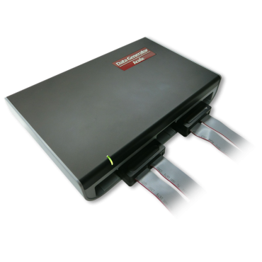
DG3064B has 48 independent channels, each channel can independently
generate digital signals, making it suitable for multi-channel
system testing.
It is used for signal simulation and reproduction. You can use
commands to control signal sending rules, import different signal
source data files or edit the signal format yourself.
Supports multiple communication protocols, including MIPI I3C, SVI3,
SVID, etc. It can be used to test and verify communication
interfaces for various applications. During the research and
development stage, a digital waveform generator can be used to
simulate and generate data and send it to the IC for verification
testing. Assists in confirming the correctness and performance of
the IC and enabling the IC to operate as expected in actual
applications. Helps identify and solve potential problems in advance
and ensures the successful application of products in the market.
power supply | 12V Power adapter |
Static power consumption | 9W |
Instantaneous maximum power consumption | 24W |
Hardware transmission interface | USB 3.0 |
Number of data output channels | 48 |
Memory depth per channel | 256MB/ch |
Data output speed | 400Mbps@Ch (Max.) |
Internal operating frequency range | 1Hz ~ 400MHz |
Internal operating frequency accuracy | 6 digits |
External operating frequency range | <200MHz< /td> |
External operating frequency mode | 1 Channel (TTL3.3V) |
trigger level | Loop, Jump, Hold, Wait for Event |
jitter clock channel | <200ps< /td> |
jitter data channel | <200ps< /td> |
Software event trigger | Hot Key |
Number of hardware event trigger channels | 16 |
Hardware event trigger mode | Logic AND / Logic OR |
Hardware event trigger trigger level | -0.5V ~ 4.5V |
Number of phase delay channels | > 300Mbps : No, < 300Mbps : 8 Phases from 0 to 1UI |
Phase delay time | All channels can be configured |