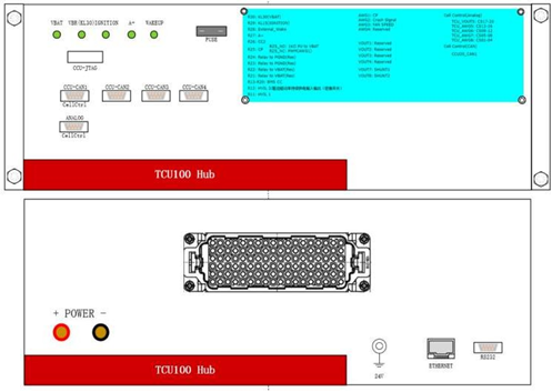
The BMS Test box
Description

Testing management Trigger Continuous logging


Main features
  • Direct transfer to computer by Ethernet or USB or RS232
  • Embedded logging in >1TB SD card
  • Testing modes and testing sequences definition
  • Limits definition
  • Trigger management

Customers benefits
  • Compact
  • Connectable to a computer and with a ready to use software tool in C# and in LabView
  • Can use directly with LabView
  • Simple and efficient to use solution to do BMS test and communication as an independent tool or as part of a system
Main features
BMS Resource list
Board DUT Signal Channel Name Channel Qty Used Remain
TCU 100 Logic Input *4ch Relay 30 16 14
Analog Input Voltage Output 8 0 8
Measurement Voltage Input 15 8 7
Frequent Output *3ch
Crash Input PWM
Leakage Censor
AWG 8 3 5
LIN *2ch CAN
LIN
2
2
0
2
2
0
Load 12 12 0
CCU 20 CAN *3ch CAN FD 6 3 3
Shunt board Shunt Simulator Voltage Output 2 2 0
Wining-board Writing all all all
NTC board NTC NTC 12 12 0
Specification
Analog Sensor Inputs(ADC Input)
  • -20V to +20V
  • Channel:8
Voltage Ouput Channels
HVIL High Voltage Interlock
  • Relays DPDT, 15 Channels
  • Relays SPDT, 15 Channels
HVIL IN/OUT
DC Signal Input(Sensors and Commands) External Wake External Wake Logic Input (Relays)
IGNITION+ IGNITION+ Logic Input (Relays)
CRASH INPUT PWM
  • Frequency Outputs
  • 8 channels

0.9Hz to 50 KHz
0.5 Hz tp 99.5KHz

CRASH_INPUT PWM Output Channels
Leakage Sensor NA Leakage_Sensor Load(Default)
Frequential Ouputs Low side fan relay?
  • Frequency Inputs, 4 channels
  • Frequency range 0.1-100K Hz
  • Duty Cycle Range 0.5% to 99.5%
LSF_01 cun monitor frequency and duty cycle
LSF_02
Charging Protocols CC Charging State Simulation CC Multiple Signal (Ref. GB/T18487.1-2015)
CC2 CC2
CP CP