General Electronics

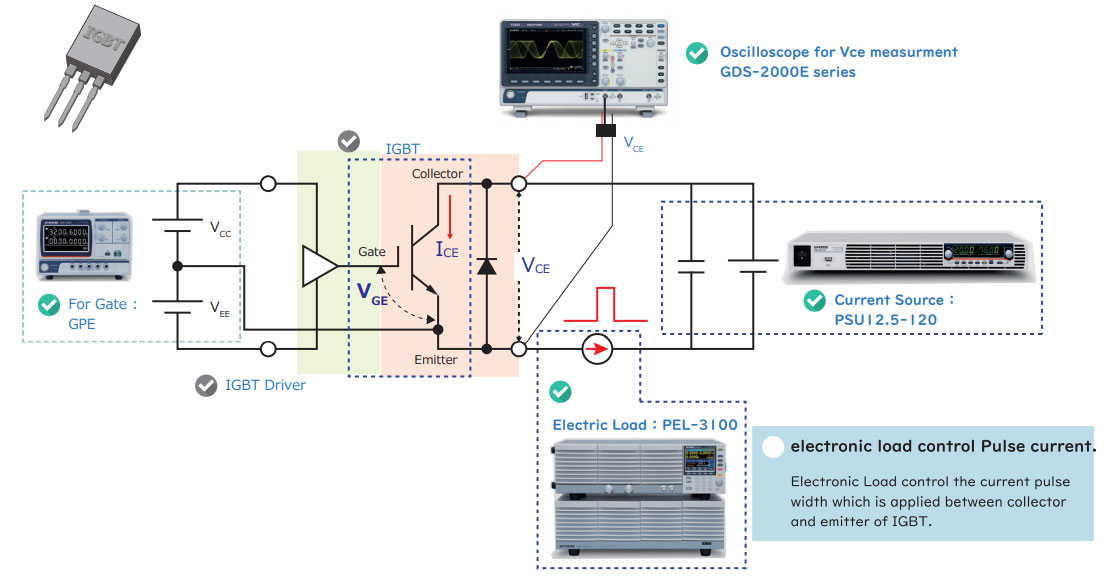
High-current I-V curve trace of IGBT using DC power supply and electronic load device

Download Download Brochure
Gwinstek Logo

In the evaluation and development of power semiconductors such as IGBT, a measurement system such as "curve tracer" that can sweep high voltage and a large current is effective.

However, those are very expensive products because those can test the various parameters of power semiconductors.

Electronic load PEL-3000/3000H can control a large current as like a pulse within tens of micro-sec. Combination of PEL-3000/3000H, PSU, and Oscilloscope can measure high-current I-V character. This combination system is useful for IGBT test at a low cost.

Test Image


Oscilloscope for Vce Measurement

Features

  • Low-cost and versatile test system

    DC Electronic load PEL-3000/3000H can control a large current as like a pulse within tens of micro-sec. Combination of PEL-3000, DC Power Supply PSU, and Oscilloscope can measure high-current I-V character. This combination system is useful for IGBT test at a low cost.

Process

  1. Set the gate voltage (VGE) in the IGBT driver
  2. The input of the electronic load is turned off. The setting voltage and current of the PSU12.5-120 are set to the maximum output state (the current does not flow unless the electronic load device is on).
  3. Turn on the electronic load device to flow the pulse current between the collector and emitter. The oscilloscope measures the voltage (VCE) of a flat portion of the peak current.
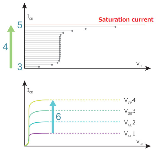
  4. Changing the current value of electronic load, measuring the Vce value by Oscilloscope and plot it's value.
  5. The point where the flowing current does not become the same as the set value of the electronic load is called a saturated current
  6. Change the Gate cntrol voltage. Repeat item 3 to 5 untill the current reach the saturation point.

The pulse current by the control of the electronic load minimizes the effect on the measured value by the generation of the IGBT.

PEL-3000/3000H can be used to vary the pulse width in microseconds, eliminating the effect of self-heating on IGBT.

Generla Electronics Graph

High resolution pulse duty cycle to control servo motors

Download Download Brochure

The pulse wave of the AFG - 303X / 302X can set the duty cycle with high resolution.

AFG-30XX series can set the pulse wave duty cycle with high resolution. Therefore, it is most suitable for servo motor design and performance evaluation.

High resolution pulse duty cycle to control servo motors

Duty Cycle Range : 0.0170%~99.983% , Resolution 0.0001%(<8.5kHz) | Duty Cycle Range (Extd.) : 0.0000%~100.0000%, Resolution 0.0001%

The settable duty times depend on the rise & fall time settings, as defined below : Duty ≧ 0.625×100×[rise time - 0.6ns +fall time - 0.6ns]/period Or Duty ≦ 100 - {62.5×[(rise time - 0.6ns) + (fall time - 0.6ns)]/period}

Servo Motor Car

Example

PWM control signal for Servo motors

FG can be used for performance test of Servomotor. The pulse duty variable resolution can be set up to 0.0001%.

Resolution Servo Motor

Features

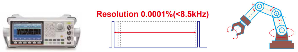
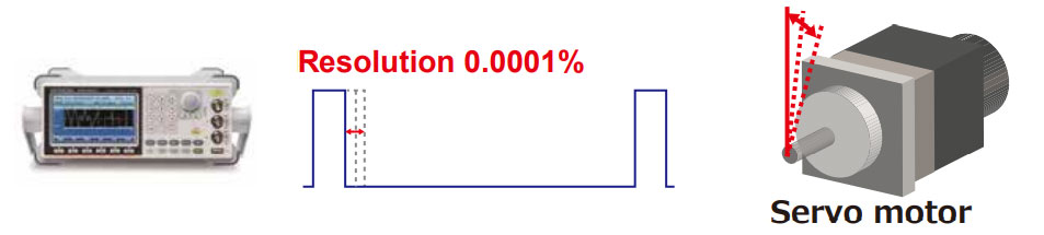
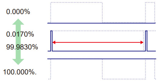
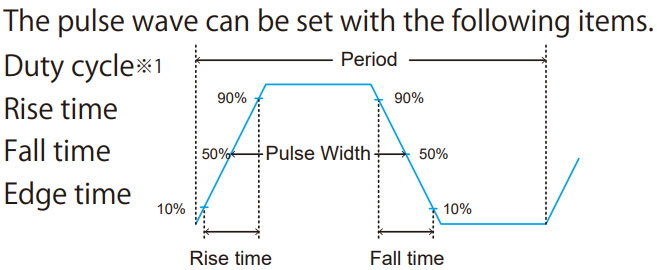
  1. High resolution duty setting
    Freq < 25MHz (20MHz AFG-3021/3022): 0.01ns pulse width (or 3 digit resolution)
    Freq < 8.5 kHz: 0.0001% duty cycle

Extended Mode

  1. The Extended Mode function extends the setting range of the pulse duty cycle to 0%100% and the setting range of the width to 0.00ns-1000ks

Duty Range (Extd.)※2

Duty Range
duty-range-2

※1:Duty Considerations: Width - 0.625 * [(Rise Time - 0.6nS) + (Fall Time - 0.6nS)] ≧ 0 Period ≧ Width+ 0.625 * [(Rise Time - 0.6nS)+(Fall Time - 0.6nS)]

※2:Loss may occur if the pulse width is beyond the setting range of the normal mode. The pulse may vanish at times.

Defect detection during motor production test

Download Download Brochure

Arc detection function of the GPT - 9900 series

In the withstand voltage test of the motor, if there is a defect such as a pinhole in the insulation between the phases of the motor, the insulating part may be denatured by heat by arc discharge. Even if there are such defective parts in a generalwithstand voltage tester, the test may be passed without being able to detect the arc discharge. Since the arc detection function of the GPT - 9900 series can also be checked whether or not such an arc discharge has occurred, it is possible to construct the production process of the arc generation inspection of the motor at low cost.

Test Image

Defect detection during motor production test

Feature

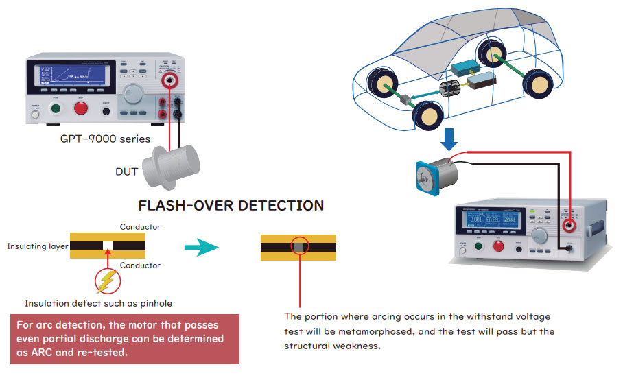
  • Arc detection funtcion to detect partial discharge
    The arc detection mode is also called flash-over. The arc detection mode detects a fast transient voltage or transient current that is not normally detected. Arc discharge usually occurs where the withstand voltage is weak. If there is a problem such as a defective electrical insulator electrically withstanding voltage, a momentary voltage or current spike phenomenon occurs. There are three arc detection modes in the GTP - 9900 series. Users can select whether to stop immediately when it is detected or to continue the test even if it is detected or end the test after detection.

The withstand voltage tester without the arc detection function will pass / fail judgment with the averaged leakage current value. The GPT-9900 series detects an instantaneous arc current of 30 μs or less, and it can be judged as "ARC" when the arc discharge is confirmed even when the averaged current value is PASS.

Measurement of leakage current of a large-capacity capacitor

Download Download Brochure

Measure leakage current of a large-capacity capacitor such as lithium-ion capacitor using DC power supply PSU capable of system up as charging power supply.

A PSU that is easy to upgrade and upgrade as a charging power supply for leakage current testing of large capacity capacitors such as lithium ion capacitors is convenient.

PSU Series

Large capacity DC power supply PSU series easy to upgrade system

Lineup of 10 models from 6V/200A to 600V/2.6A. I U (44mm), easy to upgrade system with 19 "rack size Up to 4 units can be connected in parallel.

Psu Series

The PSU series provides a maximum of 2 units in series connection (models under 300V) to achieve maximum 600V or 4 units in parallel connection to obtain maximum800Aand the maximum output power of 6.24 kilowatts.
Psu Output

Test Image

Lithium ion capacitor is a new generation product that goes ahead of electric double layer capacitor.

Lithium Ion Capacitor

Feature

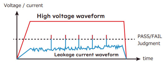
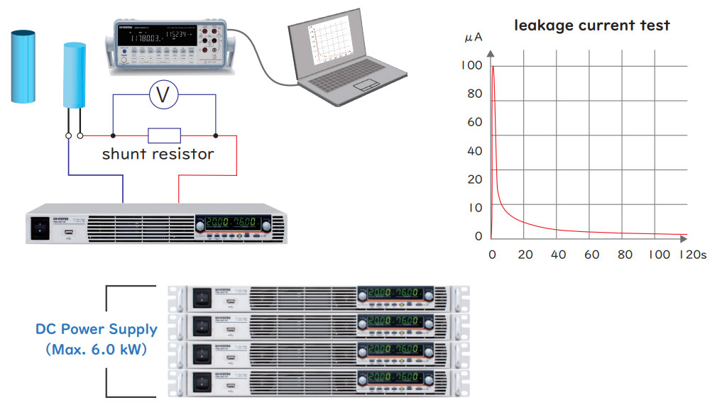
  • Pre-shipment test (leakage current test)
    Charge the capacitor with the DC power supply PSU series and measure the leakage current thereafter.
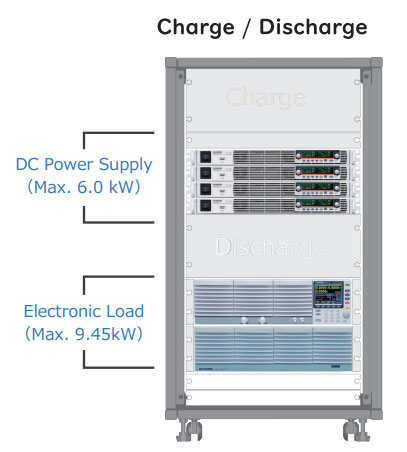
  • Charge/Discharge
    Combination of DC power supply PSU series and electronic load PEL-3000/PEL-3000H Combination test of capacitor charging and discharging.

Charge/Discharge Graph