|
|

|
|
Conduction Emission
in EMI testing is
used to measure the RF signal
transmitted through
the power system via
equipment such as LISN and isolation
transformers. For
conducted EMI tests,
other signals may be
picked up from the
environment and
wiring, causing
measurement
errors.
The purpose of this
experiment is to
help users
understand that even
with the same
equipment, different
results may occur
due to differences
in cable types,
wiring, and cable
placement.
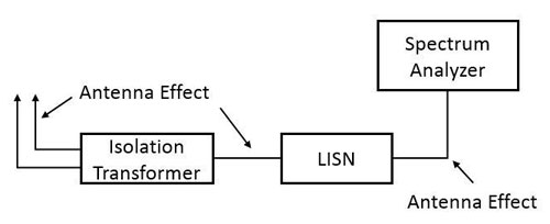
Generation of
Antenna
Effect:
The possible
generation of
antenna
effect in wiring is
shown in the
following diagram.
Factors that can
affect measurement
results include
cable
types, cable
placement, and
whether it
is floating or not,
etc.
|
|
|
|
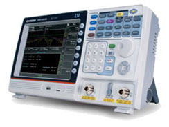
GSP-9330
Spectrum
Analyzer
|
|
|
|
|
|
Features:
|
|
|
|
|

|
Frequency
Range:
9kHz ~
3.25GHz
|
|
|
0.025ppm
Frequency
Stability
and 1ppm
aging
Rate
|
|
|
RBW: 1Hz
~ 1MHz
(3dB),
6dB EMI
Filter:
200Hz,
9kHz,
120kHz,
1MHz
|
|
|
Fastest
sweep
time:
204us
|
|
|
Sensitivity:
-149
dBm/Hz
(@PreAmp
on)
|
|
|
Remote
Control
Interface:
LAN,
USB,
RS-232
|
|
|
|
|
 |
|
| |
|
|
| |
|
| |
|
First, we used BNC
cables of different
types, including
RG58U, RG400, and
BNC
cables purchased
from an electronics
store, to connect
between the spectrum
analyzer and LISN.
Then we placed the
test system in an RF
isolation chamber
and found that the
performance of the
three BNC cables was
similar.
|
|
(Purple: RG58U,
Blue: BNC cable
purchased from
an electronics
store, Yellow:
RG400)
|
| |

(Purple: RG58U,
Blue: BNC cable
purchased from
an electronics
store, Yellow:
RG400)
|
|
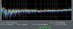
Then we moved the
entire test system
out
of the RF isolation
chamber and
performed tests
indoors. We found
that
some noise appeared
near the higher
frequency bands,
indicating that some
signals may have
been coupled in this
frequency band.
Except for RG400,
the
other two cables
picked up some
noise.
|
| |
|
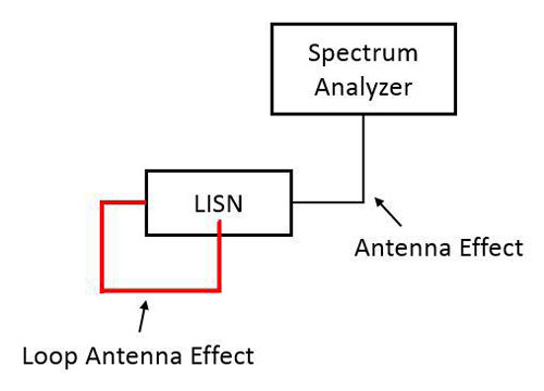
Next, we tested a
more extreme case by
directly connecting
the power cable from
the LISN input port
to LISN output port.
Surprisingly, a lot
of noise appeared.
In fact, at this
point, it indicates
that a loop antenna
effect has been
generated on the LISN, which can
easily
receive noise from
low frequencies.
|
| |
|
| |
|
In EMI labs, there
are regulations for
the placement of RF
cables or power
cables. However, in
the debug or pretest
stage, it may be
difficult to
replicate
the same environment
as the lab, which
may result in some
measurement errors.
Through the tests
described in this
article, we can see
that even in
conducted EMI tests,
|
|

(Purple/Blue:
Switching to
LISN 9 k/150kHz
filter under
normal
connection.
Yellow: Circuit
condition.)
|
| |
|
there may still be
measurement
differences due to
the
environment and
cable types. Those
are
factors that require
to be considered
when establishing an
EMI testing
environment.
For more detailed
application content,
please go to
https://www.gwinstek.com/en-global/products/detail/GSP-9330
https://www.isc4esaindia.com/spectrum-analyzers.html
|
| |

|
|
|
|
|
|
Industries
|
Products
|
Partners
|
Support
|
About
|
Contact Us
|
|
|
|
|
|